AeroCool
Steady-state heat balance simulation for modelling race
car cooling systems
You can use AeroCool to size oil and water heat exchangers, compare
the efficiency of different matrix cores, predict coolant temperatures and
define intake aerodynamic efficiency requirements.
It is aimed at professional aerodynamicists and cooling system designers
wanting to define new systems or analyse existing ones. Some basic knowledge of
cooling system layout is needed to make the best use of the program but AeroCool
is an expert system that encapsulates the calculation required within a
user-friendly interface.
Major features
 Simple
system design
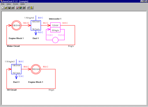
You start with a blank system containing empty oil and water circuits then
interactively add any number and combination of heat sources, passes through
the engine, radiators in air ducts and intercoolers. Once defined any element
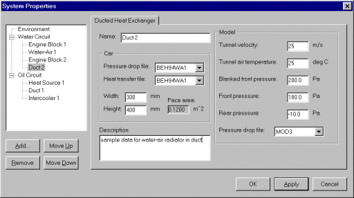
can be moved around the system or deleted. The properties for each element are
set in a Properties dialog that checks all entered values and gives
informative warnings if any are invalid.
 Sophisticated
face velocity calculation
AeroCool automatically calculates the face velocity for ducted
radiators by applying a sophisticated and proprietary energy balance method
that uses the model and actual radiator core pressure drop characteristics and
pressures measured on the wind tunnel model. This method compensates for
different pressure drop/face velocity characteristics between the model and
actual radiator cores, and for different freestream and matrix face velocity
ratios. If wind tunnel curves are not available a best estimate can be used
instead.
 Automatic
speed and throttle range calculation
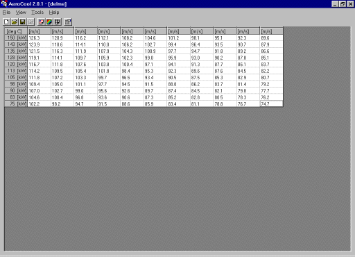
You can easily define a range of values for car speed and a separate range of
values for engine heat rejection (corresponding to a range of throttle
positions). AeroCool automatically performs full system stabilisation
calculations for each point in this 2 dimensional range. With the speed and
heat rejection range feature you can instantly characterise the performance of
your cooling system throughout all real world operating conditions.
 Multiple
system channels
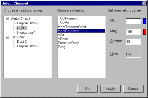
For a given steady state system condition a number of channels are calculated
for each type of heat exchange element. For example for a radiator in a duct
the following channels are available:
- Coolant exit temperature
- Exit temperature from the air circuit
- Heat transferred from liquid to air circuits
- Pressure drop across the matrix core as a coefficient
- Drag force on car resulting from pressure drop across matrix
- Matrix air face velocity
- Velocity ratio of matrix to freestream air flow
 Choice of output methods for results
You can view the system state for a particular combination of throttle and
speed as a graphical system diagram showing coolant path, system elements,
coolant stabilisation temperatures and various key system values. This summary
view is a great aid to understanding how your cooling system is working.
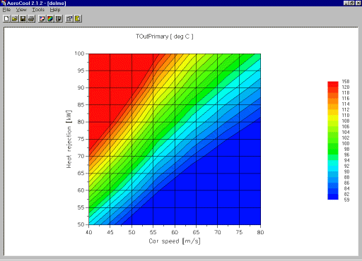
The speed and throttle range results for any calculated system channel can
be seen as either a table or as a coloured contour plot, giving
an immediate visual or quantitative summary for a wide range of throttle and
car speed conditions. You can alter the formatting of the range plot for each
channel, and any changes you make are stored for later reuse.
 Easy
file management
Complete systems can be saved to and restored from disk in one operation,
making it easy to manage multiple scenarios and modify previous systems.
 High
quality printouts
You can choose to print any combination of contour view, table, system diagram
or a text listing of all input data in one operation. This allows you to get a
complete hardcopy record of any analysis for presentation or future reference.
|